DSS5800
8VSB Decoding Drive Test 시스템
DTV 신호의 측정에 폭 넓게 사용가능.
차량에 부착하여 이동 중 측정 가능. GPS장착
Swept 스펙트럼 전계 강도 측정기와 8VSB Decoder가 PC의 조절에 의해 연동되어 사용.
측정 데이터 : power, tap energy, peak power, 8VSB MSR, SNR, SER, in-band tilt, hi/low difference DSS5800 Drive Test System Specifications:
Third Order Intercept: Preamp ON typ. 0 dBm Preamp OFF typ. +20 dBm
Noise Figure: Preampli er NF 7 dB typical when RF
AMP is selected.
Audio Detection: AM or FM to internal speaker selected
from front panel Sensitivity
FM detection: 1 mV for 12 dB SINAD typical
AM detection: 1 mV for 12 dB S/N typical
System Measurement Resolution: 0.1dB
Output Linearity Range:
Continuous measurement range of 80 dB in auto-rang-ing mode
IF Bandwidth: Narrowband 15 KHz Wideband 150 KHz
Input Impedance: 50 Ohm
DECODER SYSTEM SPECIFICATIONS
Class of Decoder: 8-VSB Decoder Description: The Decoder Module is an ATSC compliant demodulator with forward error cor-rection decoder and concatenated trellis (Viterbi)/Reed-Solomon decoder with deinterleaver/de-randomizer. Decoder features 6 MHz wide IF bandwidth Square-Root Raised-Cosine lter Fully internal carrier recovery loop Fully internal symbol timing recovery with programma-ble loop lters Adaptive Equalization, including feed forward and feed-back sections (DFE structure)
Range of -2.3 uS to +22.5 uS by default.
User extendable to -2.3 uS to +80uS.
Adaptation based on ATSC eld sync (trained) and/or
8-VSB data (blind). Equalizer Taps: 900 Total Taps
25 Pre-Taps Represent -2.3329375uS
874 Post-Taps Represent + 80.28072uS
Decoder Signal Parameter Measurements and Storage
Parameters Measured & Recorded to Data Files :
1)Sync Lock (True/False)
2)Equalizer Lock (True/False)
3) Main Tap Energy
4) Total Tap Energy outside Main Tap (dB)
5) Signal to Noise Ratio before correction (SNR)
6) Segment Error Rate (SER)
7) Mean Square Error out of Equalizer (MSE)
Forward Error Correction:
Trellis (Viterbi) decoder Rate 2/3 (Rate 1/2 Ungerboeck code based) (207, 187, T10)
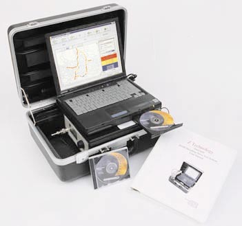
DTV (8-VSB) Terrestrial TV Broadcast Measurement System is a Windows based system housed in a compact suitcase sized package. The system provides all the capability of an RF Drive Test Signal Level Measurement System with the addi-tion of 8-VSB Digital Television Signal Decoding. The DSS5800 offers extensive RF and 8-VSB decoded parameter measurement capability. The DSS5800 is designed for automatic data mea-surement, collection and storage. Parameters are stored in open format comma delimited data les. Data can be plotted in color over maps of coverage areas. Collected data is available for analysis, print out and easy export to several other programs.
SYSTEM RF SPECIFICATIONS
Frequency Range: Coverage of all VHF & UHF System M Television Channels (2-69)
Extended coverage: 5 -1000 MHz contiguous coverage with minimum step size of 1KHz
Measurement Range: -10 dBmV to + 90 dBmV (-117 dBm to -17 dBm) using 4 internal Attenuation Ranges & 1 Preamp Range
Measurement Accuracy: +/-2 dB @ 25 degrees +/- 10
degrees C. in Field Strength Meter Mode Typical in Sweep Modes & for temp. range of 0 to 50 degrees C.
Some modulation types in uence measurement accu-racy. For analog video modulation, the signal level of the Vertical Sync Peak is measured. This adds 0.5dB additional uncertainty, widening the above speci cation to +/- 2.5dB. Power Readout Capability: dBm, dBuV or dBuV/Meter (dBuV/M reading requires optional calibrated antenna) RF Signal Parameters Measurements and Storage Parameters Measured & Recorded to data les Band-pass settable from 1 -- 8 MHz):
1) Total Integrated Power
2) Peak Power
3) In-Band Tilt
4) In-Band Notches(Hi-Lo Diff)
5)In-Band Std Deviation of Power
Decoded Signals Measured & Recorded to Data Files: See Decoder Section Below
Image Rejection: 60 dB typical, High Sensitivity mode
Detuning Characteristics: 40 dB typical; for undesired
DSS5800 Drive Test System Specifications(Cont.)
For additional information please contact the factory.
DGPS accuracy Position: 2 m CEP (50%)
Velocity: 0.05 m/sec
Acquisition (typical)
Cold start: <130 seconds(90%)
Warm start: <45 seconds(90%)
Hot start: <20 seconds(90%)
Cold start requires no initialization. Warm start implies last position; time and almanac are saved by back-up power. Hot start implies ephemeris also saved. Reacquisition after signal loss < 2 seconds (90%) GPS antenna Compact, active micropatch antenna with 5-meter cable & mag. mount. 1.60” x 1.90” x 0.55” high (40.6mm x 48.3mm x 13.9mm)
COMPUTER
Laptop Computer: Windows OS, Speed of 600 MHz or better and at least 64 Mb Memory
SYSTEM PHYSICAL SPECIFICATIONS
System Power Requirements: 12VDC at 3.5AMP or 120/220VAC
Power Inverter: 12V DC input 120V AC output, 150 watts Certi cations: UL CSA
System Dimensions: 216 mm (8.5 in) High 375 mm(14.75 in)Deep 470 mm (18.5 in) Wide
System Weight 13.9 Kg (29 lbs.)
System Operating Temp: +10 to +40 Deg. C
Options:
MD 01 Real-Time North American Map Data
MD 02 Real-Time European Map Data
MA 03 Post-Measurement Delorme Street Atlas USA™
MA 04 Post-Measurement Microsoft MapPoint ™ USA
MA 05 Post-Measurement Microsoft MapPoint ™ Europe
MA 06 Post-Measurement Custom Mapping
Accessories:
AA1-B1: Calibrated tuned dipole antenna 30 - 70 MHz
AA1-B2: Calibrated tuned dipole antenna 65 - 180 MHz
AA1-B3: Calibrated tuned dipole antenna 170 - 340MHz
AA1-B4: Calibrated tuned dipole antenna 325 - 1000 MHz
AA-TV SET: Calibrated tuned dipole antenna Set 57 - 806 MHz
AA-3 Biconical antenna system 20 MHz - 330 MHz
AA-4 Log Periodic antenna system 290 MHz - 1000 MHz
AA-6 Log Periodic antenna system 150 MHz - 1000 MHz
AA-7 Bi-Log Periodic antenna system 25 MHz - 1000 MHz
Reed-Solomon code Internal convolutional de-inter-leaving (I = 52; using internal memory) External indication of uncorrectable error (Transport Error Indicator bit in MPEG packet header is also set) De-randomizer based on ATSC standard NTSC co-channel interference lter NTSC co-channel interfer-ence technology with low noise penalty
APPLICATIONS SOFTWARE, DATA STORAGE & DATA FORMATS
Applications Software: Windows 95/98/XP based Automated Drive Test Measurement Software includes the following
1) Data Collection: Provides for orderly collection and storage of RF and Decoded Figures-of-Merit Parameters outlined in the above sections.
2) Dot Plotting/Mapping: Allows GPS locations to be plotted and viewed during and after testing. Colors are assigned to the dot trail of the driven path and indicate range of parameter. Colors correspond to any one (1) selected RF or Decoded Figures-of-Merit Parameters.
3) Sweep Analysis: Displays
a) Swept frequency spans: 5MHz, 10MHz & 20MHz RF Parameters calibrated in 10MHz & 20MHz (150KHz BW)
Acquisition Sweep Rates in these two modes: 550msec per sweep Sweep refresh rate depends on Decoder settings
b) Tap Energy Plot (Echo Pro le): All measured RF & Decoded Figures-of-Merit Param-eters are displayed for users review and analysis. Data Storage: Data Stored on PC Hard Drive under open folder and le hierarchy
Data Format: Format is comma delimited nonpropri-etary les accessible for importing into other standard utilities. Data recorded into les include: date, time, freq, latitude, longitude, elevation, speed, power, inte-grated power, peak power, tilt, high-low diff., std. dev, tap energy, main tap, SNR(dB), MSE, SER, Sync Lock, EQ Lock.
GPS RECEIVER AND ANTENNA SPECIFICATIONS
General Description: L1 frequency, C/A code (SPS), 8-channel continuous tracking receiver, 32 correlators
Antenna Connector: SMB
Update rate: 1Hz
Accuracy: Position & Velocity: 25 m CEP (50%) & 0.1 m/sec (without S/A)Time: 95 nanoseconds RMS (over-determined clock
|
 DSS5800_System_ds_dss5800.pdf (2.047MB)